The Kyodo was originally designed by Grundig. As far as I know the design was released under the names Grundig, Kyodo, Key,
Elin and Dacota. There is no difference in terms of electronics. Basically the transmitter/receiver equipped with 16 channels.
There are also versions with 40 channels, but these are practically untraceable. In general, the design is as shown below.
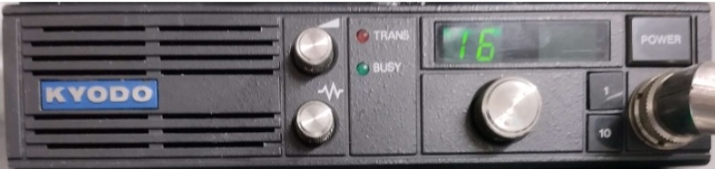
The simplicity of the operation makes the transmitter/receiver very pleasant to use. However, for the radio amateur the
16 channels are very limiting. The front of this transmitter/receiver shows the following functions:
- Volume control
- Squelch
- Channel selector
- buttons 10 and 1 for the tone lock.
This is not applicable for amateur use. After removing the front and dismantling the electronics present, the printed circuit
board with the above-mentioned is exposed, as shown below.
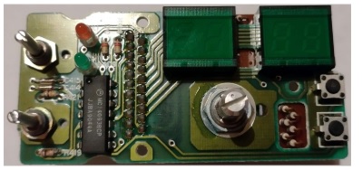
The potentiometers for volume, squelch and channel selector are connected to the base board in the front by means of a
flex print. Research has shown that this printed circuit board can easily be replaced by a new printed circuit board with
functions aimed at the radio amateur. A new printed circuit board was therefore made using KiCad, as shown below.
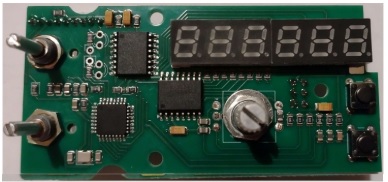
The core of the design has been converted around the ATMEGA328 microprocessor, well-known from the Arduinos. The
software has been written in assembly using Microchip Studio. This is to save as much space as possible in the program
memory of the processor. The software is universal for many frequency bands of Kyodo. By pressing the 1 and the 10
button and the power on the device a menu appears. By rotating the encoder you can select the transmitter. By pressing
the PTT on your microphone the software for the device is confgured. The interfacing to the display and the segments is
via two pcf8574 I2C to 8-bit I/O chips. The channel selector has been replaced by a rotary encoder. The potentiometers
for the volume and the squelch can be transferred to the new printed circuit board.
The displays of the channel display and the tone lock have been replaced by six 7-segment displays. The TX and Rx LEDs
have not yet been mounted, because they have to be positioned precisely in the front. The result of the conversion is shown
below.
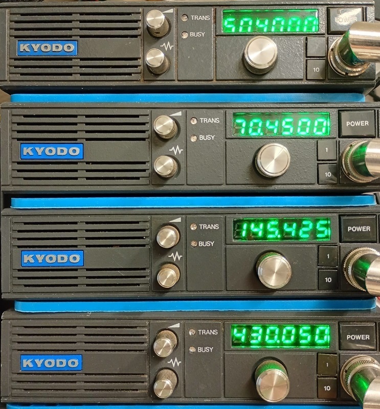
Originally, the 16 channels are selected by means of an EPROM in which the frequencies for transmitting and receiving are
programmed. By making a small change to the PLL print, it is possible to replace the EPROM completely by a pcf8574 I2C
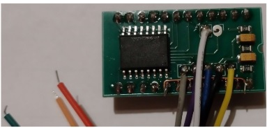
to 8-bit I/O chip. Instead of the EPROM, a piggyback is placed with the I2C I/O chip. The processor on the base board
simulates the function of the EPROM. The piggyback sends for the synthesizer in succession according to:
- the addressing MC145146 synthesizer of the latches
- the data for the MC145146 synthesizer latches
- the ST signal (store/strobe) for the MC145146 synthesizer.
The piggyback also provides the (5 volt) power supply to the base board and the reading of the PTT for the switching to
transmitting. A total of 9 wires are led to the chassis of the kyodo by means of a connector. Six of them go to the piggyback.
The three remaining are respectively for:
- display Tx LED normal mode RED, repeater mode BLUE
- display Rx LED normal mode GREEN, repeater mode BLUE
- injecting the CTCSS signal into the Tx audio.
An image of the biggyback is shown below.
This change makes the following functions available for the Kyodos:
- Kyodo KG105/15D or equivalent, frequency range from 144 MHz to 146 MHz
- Kyodo KG105/8?? or equivalent, frequency range from 70,0 MHz to 70,5 MHz
- Kyodo KG105/40B or equivalent, frequency range from 430 MHz to 440 MHz
- grid adjustable from 12.5 kHz and 25 kHz, 50 kHz adjustable with encode
- repeater use for 2 m band -600 kHz
- repeater use for 70 cm band +1,6 MHz or - 7,6 MHz auto select
- listening to the repeater input during repeater use
- adjustable CTCSS from 67,0 Hz, 71,9 Hz, 77,0 Hz, 79,5 Hz, 82,5 Hz, 88,5 Hz, 94,8 Hz, 100,0 Hz, 103,5 Hz, 110,9 Hz,
114,8 Hz, 118,8 Hz, 123,0 Hz, 127,3 Hz, 131,8 Hz and 173,8 Hz adjustable with encode.
The repeater function is set with the two, first unused, push buttons.
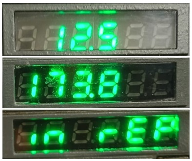
In principle, the above settings are loaded while pressing the PTT. If no microphone is connected, the settings are saved
by pressing the bottom push button. Transmitting outside the frequency range of the transmitter is not possible. If transmission
is made outside this frequency range, the transmitter automatically switches back to normal mode.
For more information mail me. For this project you can chat on WhatsApp
See for more details: Modify Kyodo 105 series or PE1NZI - Callsign Lookup by QRZ Ham Radio


